Europe is an interactive educational game for children (and adults). It was quite a big project spanning several months and several people with different specialisations were involved. The official opening was on 22 April 2016. This article describes design decisions for electronics, implementation and lessons learned.
My colleague Michal Valoušek asked me to help him with this project sometimes in 2015. But due to various circumstances (mainly financial reasons and lack of free time) we began actual work in January 2016. The main idea was conceived by Ivo Skoček and Jiří Palát from Červotoč (červotoč means wood-worm in Czech language and it is also the name of their woodworking company). Michal Valoušek designed and programmed the software running on Linux computer, the graphics, photos and sound effects were provided by Ladislav Krajča, Honza Bednařík made 3D printed parts and I built hardware and wrote the firmware.
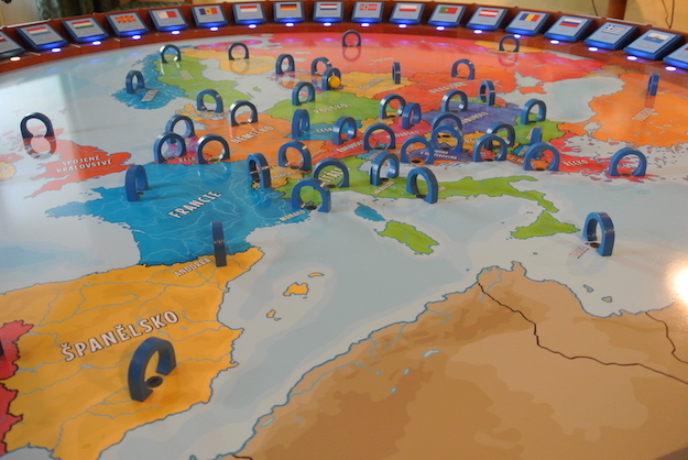
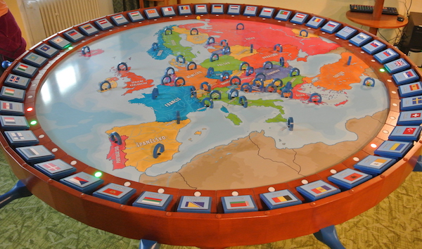
The game principles are simple: there are 48 gates positioned on main board (which is a map of Europe), each representing one state. Team of players has to answer to several questions by putting wooden marble through the right gate. They are not allowed to directly touch the marble, though. Main board is anchored to spring on metal leg, players only choice is to tilt board and let the gravity do its work.
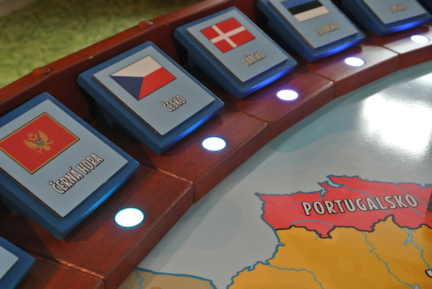
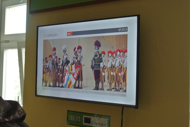
The game’s computer generates random questions about Europe (the location of the state, to identify national flags, what is on the picture, etc.) and displays them on LCD display mounted on the wall. When marble goes through the gate, electronics integrated in a board detects this event and sends message to computer which evaluates if the answer was correct or not.
In the rest of this article I will describe how electronics was made and what problems we had to solve.
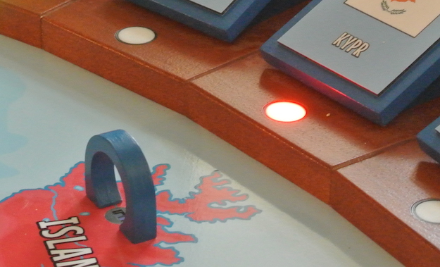
Short demo. As soon as marble goes through correct gate, the green LED near correct state will blink and new question will be displayed on LCD.
Technical Requirements
- There are 48 gates on the main board. Each gate has to independently detect wooden marble.
- The gate’s installation should be as easy as possible and should be done from the bottom.
- Board thickness is around 4 cm. All electronics and cables should be positioned in shallow grooves in plywood.
- There will be RBG LEDs positioned on the edge of the main board. Each LED will represent one state and should blink and signal game progress to the players.
- Main board will be in the middle of the room and computer with LCD on the wall. It means the cable between computer and board should be at least 3 to 5 meters long. Cable will be hidden under the carpet.
- No wires should be visible.
- Everything has to be firmly connected to the board. Connectors should not disconnect by themselves.
- After the installation, access to electronics or cables will be difficult.
I did not want to use Arduino or some universal development board mainly because of their thickness. The board itself is only 40 mm thick and Arduino with some shield mounted on it can be 26-30 mm (Arduino Uno has 13 mm, shield with some connectors can be 13 to 20 mm thick). Oh, and I just wanted to design my own PCB :)
The first idea was to make simple PCB with cheap microcontroller, IR LED and IR phototransistor. All 48 gates/PCBs would be daisy-chained together and from the computer point of view it would act as large shift register (or maybe (OneWire)?). This idea was declined as well mainly because the price of such solution (the ATTiny13 costs little more than $1, that is approx. $50 just for MCUs).
I have experience with AVR architecture, so that was my first choice. The ATTiny10 or ATTiny13 were considered. Gate PCB had to contain data input, clock, data output, signal for LED and phototransistor – 5 signals in total. The ATTiny10 has 4 GPIO only (and that means you will disable reset in fuses), so it could not be used. ATTiny13 has 5 GPIOs (6 with disabled reset) so this is better candidate. Because clock signal would be generated from master device, the internal 8MHz RC oscillator inside each ATTiny13 would be sufficient. There is one problem, though. The cable length for all gates would be more than 10 meters (up to 5 meters from computer to board and 48× 10, 15 or 20 cm between the gates). Such long cable would have quite high resistivity and capacitance resulting in slow communication speeds. The voltage drop at the end of chain would also be significant. Not to mention the possibility of noise on such long bus.
Because of approaching deadline (the official opening of this game) I did not want to experiment with new architectures like MSP, PIC or something. I decided to stick with AVR family because I have the most experience with it.
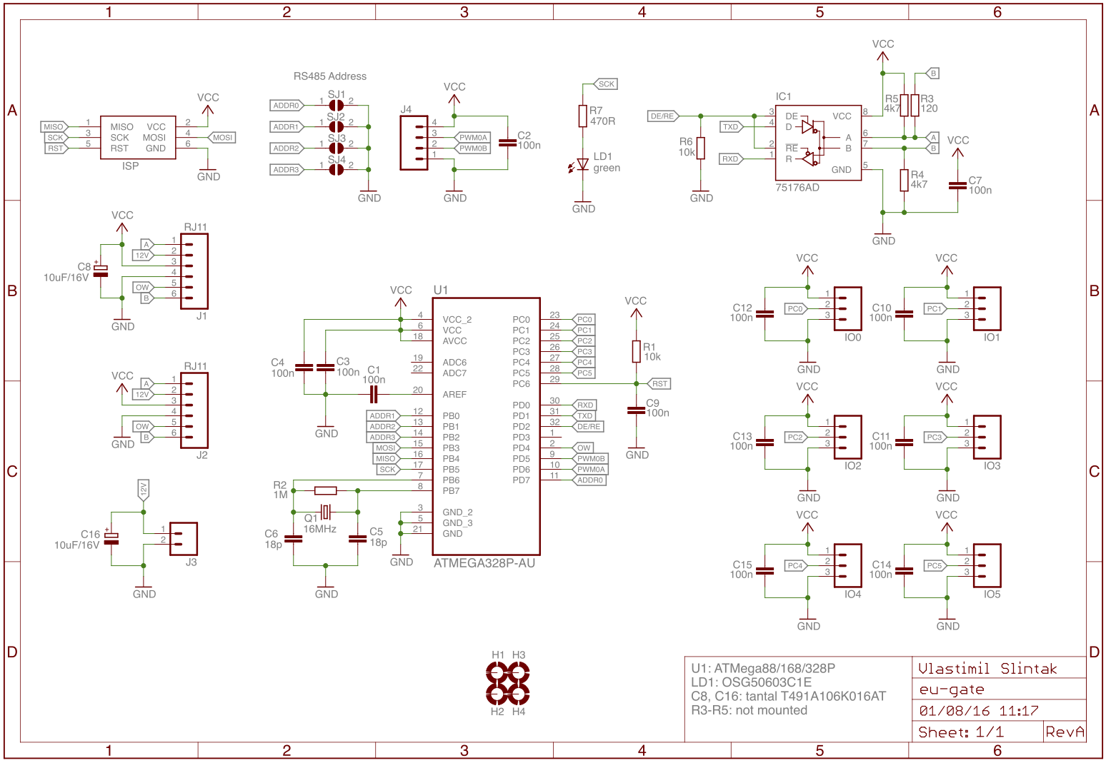
The final idea was to use ATMega88P (from the same series as ATMega328P in Arduino Uno) with plenty of GPIOs. Each PCB can sense marble from up to 6 gates – it means it will be necessary to make 10 boards. And of course there is one important advantage – bootloader. It will be possible to update firmware in all MCUs from the computer without disassembling whole game.
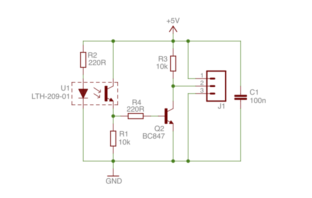
Apart from gate PCB (I call them eu-gate) the small PCB with just IR LED and phototransistor was designed. Those are called eu-ir and are connected by short 3-core flat cable to the nearest eu-gate. Firmware checks state of all connected IR boards and stores their states until bus master (the computer) reads them.
All eu-gate boards will be connected together and form a RS485 bus. This bus is suitable for long distances because it uses one differential pair in half-duplex system – unlike I²C or SPI which are designed for short distances. The UART itself could also have some problems with noise.
The wire used for bus (connecting all eu-gate board) has to have at least 4 cores, one for power supply (VCC, 5V), one for ground (GND) and two for differential data (called A and B in RS485). Here I made the first mistake in the design. I planned to use this wire also for the power supply. More about this in the next section.
The used bus is half-duplex, meaning the device can send or receive data. It is not possible to send and receive data at the same time. If there is need for full-duplex communication, another pair of data wires and one more SN75176 would be needed for each device on the bus.
The Modbus is used as communication protocol on this bus. This is quite old (late 70s) and very simple protocol. It can be used on half-duplex buses and there can be exactly one master and several slaves. Master initiates transmission by sending packet with read or write request and slave sends response. Each slave has to have unique address and master can choose which slave should respond to its request.
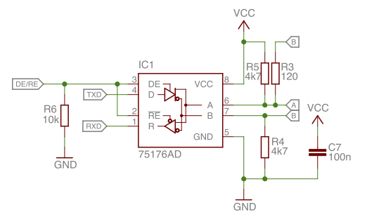
The microcontroller (in this case ATMega88P) needs three GPIO for RS485/Modbus. One signal is DE/RE which selects if SN75176 acts as receiver or transmitter (by the way, the selection of SN75176 was mistake #2). Second and third signal is RX and TX, respectively. Those signals are connected to UART pins on ATMega88P, thus hardware UART can be used for Modbus. Resistors R3, R4 and R5 are not used. Resistor R3 is for impedance matching and should be used only at the beginning and end of the RS485 bus.
Brief description of Modbus over RS485: when the bus is idle, all connected devices should be in receiving state. If master wants to initiate communication with one of the slaves, it sends packet with read or write request. This packet consist of slave address (8 bits), function number (8 bits, 0x03 for reading or 0x10 for writing, there are more functions defined in Modbus standard), number of registers to read/write (16 bits), register address (16 bits), data are present in case of write request (n×16 bits) and CRC (16 bits). As soon as the slave receives whole packet it checks CRC and slave address. If CRC is correct and slave address is its own, it will evaluate master’s request (writes data into or gets data from given registers) and immediately sends response. After the response is send and received by master, the bus goes into idle state again.
In our case, the firmware in each eu-gate board has three Modbus registers:
0x00000x00XX; IR gates state since last Modbus reading or FW reset.0x00010xXYYY; firmware (Y) and hardware (X) version.0x0002reset; any writes to this register will trigger FW reset in 500ms.
The master of bus (computer with USB-RS485 converter) has to periodically check register 0x0000 in all connected slaves. If any IR gate was triggered by the wooden marble, the value of this register is non-zero and software in computer can decide what to do next.
The slave address can be set by four solder pads on PCB. These pads are connected to MCU’s GPIO and can be read by firmware. It also means there can be up to 15 boards on one RS485 bus. If more boards are needed on one bus, the address has to be set in different way (stored in EEPROM, more solder pads on PCB, etc…).
The standard ethernet cable Cat5e was used to connect all 11 eu-gate boards. Only three pairs (6 wires from total 8 wires) were used and crimped onto RJ12 (6p6c) connector. One pair is used for power supply (5V and GND), one pair is for Modbus (signals A and B) and one pair is for future use (I was thinking about 12V and OneWire, but for now I didn’t use it).
As mentioned before, the Europe board contains several RBG LEDs around the edge of board. These LEDs are WS2812 a.k.a. NeoPixel. One eu-gate board with special firmware was used for controlling these LEDs. This board is connected to Modbus network just as any other board in game. Each of the LEDs is represented by one Modbus register so it is possible to turn LEDs on and off by writing register to correct Modbus slave. The LEDs are daisy-chained and data signal is connected to board’s PWM0A pin on connector J4.
The bus master is small computer with GNU/Linux OS (Intel NUC and Debian OS). The used technology: Django (for web interface), Python (with pyserial library to communicate with game via Modbus), Docker and Ansible.
All source codes, Eagle files, BOMs, etc. can be found in project Git repository, hardware directory.
Build
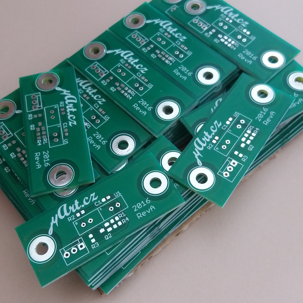
Both PCB types for this project were made in local PCB company. They have minimum order quantity so 15 pieces of main PCB (eu-gate) and 60 pieces of eu-ir had to be made. It means I have few extra boards for future projects :)
The game board contains 11 eu-gate PCBs (10 for checking IR gates and 1 for driving RGB LEDs) and 48 pieces of eu-ir. These small boards have IR LED and transistor in square plastic package, so we 3D printed round adapter for easier installation.
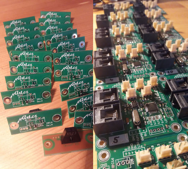
Assembled and finished boards are shown on the top picture. The square IR photo-interrupter can be seen on left bottom part of picture. Right side of picture shows assembled eu-gate boards with all connectors and parts. The Modbus addresses were already assigned to all boards by soldering pads SJ1 to SJ4.
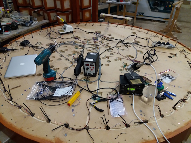
The installation of all electronics and cables took several days and was done in Valašské Meziříčí (CZ).
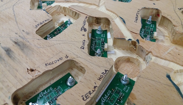
The bottom side of plywood was milled so eu-gate and eu-ir could be positioned in correct places. After this was done, all cables were cut to correct lengths and crimped with connectors. Main eu-gates PCBs are daisy-chained by ethernet cable with RJ12 connectors and 3-core flat cables with KK254 connectors were used for eu-ir boards.
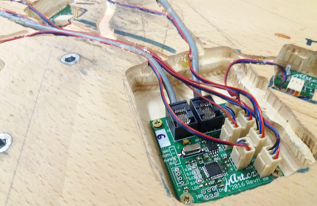
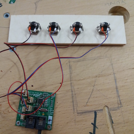
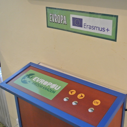
These two photos show the wooden box with computer and three buttons for user-interface. These buttons are connected to one eu-gate PCB and connected to PC via RS485/Modbus.
Mistakes
Europe game was a huge project and some mistakes were done. Here is the list of some design and electronics problems we had to solve.
First big and stupid mistake was insufficient power distribution. All main and IR boards are powered by 5 Volts and for its distribution one pair of wires in ethernet cable is used. I did not think of voltage drop on these wires over long distance (and believe me, 10 meters of ethernet cable is long distance). I wanted to lower manufacturing price and did not use any voltage regulator or DC/DC converter in main eu-gate boards.
Second mistake was to use SN75176 for RS485 bus. This really old part is cheap but has big consumption. Even in idle mode. According to data sheet, the maximum current is 50 mA at 5V. For example the newer and the more expensive part is ST485. This chip has current consumption less than 1 mA!
As soon as we powered all electronics I realised both mistakes. The voltage at the end of RS485 bus was less than 3 Volts. This is too low for SN75176 to work without any problems. Also ATMega88 with 16 MHz crystal also needs 4.5 V or more to be reliable.
Here is some maths: one eu-gate board has maximum current consumption 60 mA (50 mA for SN75176 and 10 mA for ATMega88). One eu-ir needs 18 mA with IR LED powered on. Whole game board needs 10 × (60 + 6 × 18) = 1680 mA! The resistivity of ethernet cable is around 0.188 Ω per meter, so we have 0.315 Voltage drop per meter. If game is 3 to 5 meters far from power supply, we have 4.052 to 3.425 V on first eu-gate board.
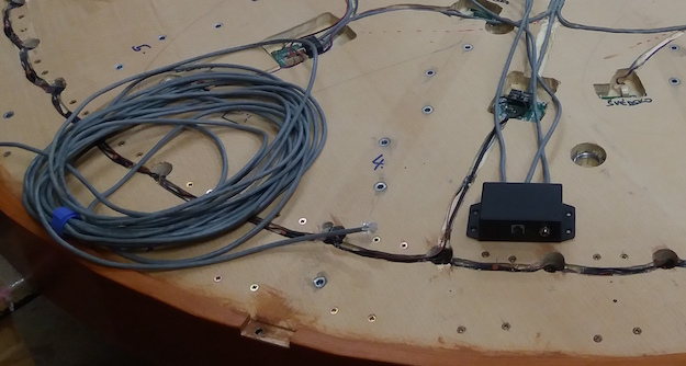
To fix these mistakes, we had to move power supply to game board as near as possible. Fortunately there was some empty space in metal leg on which main game board is installed. The small plastic box with RJ connectors and power jack was made and together with 5V/5A power supply installed inside this leg.
Next mistake – I should’ve designed small PCB for WS2812 LEDs together with capacitor and connectors for easy installation into plywood board. The THT version of these LEDs has 4 pins in round 5 mm package. We designed and 3D printed fixture for LED, reflector and LED cover, soldered wires directly to the LEDs and then installed into holes in plywood. Then it was necessary to solder each LED together. This was tedious and exhausting job. This would be easy and fast with custom PCB and crimped wires without need for soldering.
Another small problem was with connectors KK254 used for connecting eu-ir together with eu-gate. These connectors has 2.54 mm spacing and are too high. Because of that, the milled holes for eu-gate boards had to be deep. Fortunately this was just few millimetres, but still I could’ve used smaller connectors 2.0 mm PH-JST.
Here is the summary of all mistakes. If I ever do another Europe game, I will change:
- Step-down DC/DC converter or linear regulator for each eu-gate board. Then I could use 12 or 24 V power supply and voltage drop over ethernet cable wouldn’t be a problem.
- Never again use SN75176. ST485 or some other pin compatible version is better.
- Soldering wires directly to pins on LEDs is a lot of work. Better to design custom PCB with all necessary connectors and parts.
- To safe space, use smaller JST connectors instead of KK254.
Successes
Design and layout of both PCBs is good and does not contain any problems. Everything worked on first try.
Combination of RS485 and Modbus is very reliable and easy. There are no problems with communication over 10 meters with twisted pairs in UTP Cat 5e cable. Also ethernet cable is cheap and easy to find.
ATMega family with bootloader support was good choice. The Modbus bootloader I made for this project was useful because we changed firmware several times during first days.
Soldering pads for Modbus slave address are easy to use and reliable. First idea to use EEPROM and set address during programming would be problematic (for example to change address in spare board you need only soldering station and not an AVR programmer).
Two spare pins on RJ12 connector weren’t needed. I could have used RJ11 (4p4c) and save some space on PCB.
Firmware
Complete project — software, hardware and firmware — can be found in Git repository on Github. There are Python examples on how to use Modbus in directory hardware. The firmware itself is written in C language and Makefile is used to compile all things together.
Firmware for IR gates detection and keyboard is in directory hardware/src. The special firmware for controlling WS2812 (Neopixels) can be found in directory hardware/neopixel. Directory hardware/bootloader contains RS485/Modbus bootloader written and tested for ATMega88, ATMega168 and ATMega328. The bootloader needs less than 1 kB of flash and around 350 B od RAM.
Conclusion
The official opening was on 22 April 2016 in Valašské Meziříčí. The game was played by several dozen children and adults during few hours. I am happy to say everything worked without any problem during this time.
Few more photographs of game board and LCD TV with user interface: