If you follow me on Twitter, you may have noticed that since January 2024, I’ve been experimenting with the LoRa mesh network Meshtastic. I’ve already written several blog posts on the topic, including Meshtastic in Practice, Building a Meshtastic Router, and Building a Meshtastic Router 2. I’ve published a model for the RAK19007 electronics holder and solar panel on Printables, delivered a presentation at LinuxDays, and had an article published on Root.cz (the biggest Linux and open-source magazine in Czech).
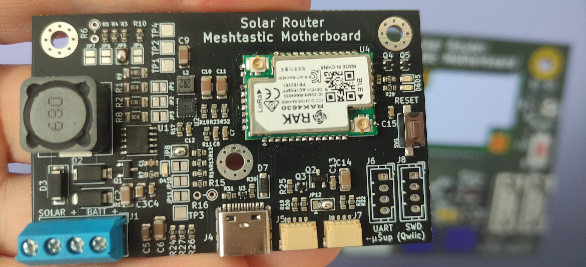
In May, unsatisfied with my solar node using the RAK4631 and RAK19007, I opened KiCAD for the first time and began designing my own PCB for Meshtastic. This post describes a solar MPPT charger for Li-Ion, LiFePo4, or LTO batteries based on the RAK4630 module.
What makes this MPPT charger interesting? Primarily, it consolidates everything on a single PCB measuring 70 × 43 mm. Moreover, you can use any solar panel with an operating voltage from 7 to 30 V and any battery with a nominal voltage lower than 5.6 V. This means the Meshtastic router can be connected with:
- 1S Li-Ion and Li-Pol (standard, widely available batteries commonly used by Meshtastic enthusiasts),
- 1S LiFePo4 (popular in solar installations due to their long lifespan and capacity over 100 Ah), or
- 1S and 2S Lithium Titanate Oxide (LTO) (batteries that can be discharged and charged even in winter temperatures below −10 °C).
Note: This article mentions LoRa mesh network Meshtastic, but any RAK4630/RAK4631 compatible firmware will run on this hardware. For example: Meshtastic, MeshCore, Reticulum and others.
Additionally, the PCB has connectors ready for easy connection of I2C sensors (like temperature, humidity, and pressure measurements or any others supported by the Meshtastic firmware), a USB-C connector (used only for communication, not powering the board), and a RESET button for easy FW updates, two signal LEDs, easy access to UART RX and TX signals and SWD (Serial Wire Debug) interface for FW development/debugging, and finally three mounting holes for M3 screws to secure the PCB into an enclosure.
I am still working on the baseboard and this text. There are four PCB revisions:
- Revision A dated 6.6.2024, sold from 8.7.2024 and 11.8.2024, unavailable now.
- Revision B dated 12.8.2024, sold from 4.9.2024, unavailable now.
- Revision C dated 1.10.2024, sold from 1.11.2024, unavailable now.
- Revision D dated 20.11.2024, sold from 15.1.2025, unavailable now.
- Revision E dated 26.8.2025, sold from 1.11.2025.
Differences between versions are explained further in the text.
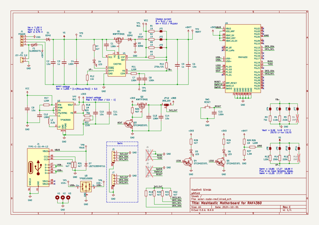
Schematic
The baseboard contains three main parts:
- an MPPT charging circuit based on the CN3795 chip,
- a buck/boost DC/DC converter with TPS63000, and
- a LoRa 868 MHz RAK4630 radio module.
Among Meshtastic builders, the RAK19007 baseboard with the RAK4631 LoRa module is popular, along with a Li-Ion battery charger based on CN3791 and one or more parallel Li-Ion cells. This was the setup I started from.
The heart of the RAK4631 radio module is the RAK4630 module (confusing, right?), which is placed on a small PCB with several resistors and a tiny SMD connector on the bottom side. Therefore, it wasn’t necessary to use the RAK4631 module, and I chose the slightly cheaper RAK4630 with IPEX connectors, which can be easily soldered using castellated holes onto my own PCB.
The charging circuit CN3791 from the Chinese company Consonance is a 4 A MPPT charger for single-cell Li-Ion or Li-Poly batteries. While browsing through their other integrated circuits, I found the much more versatile and interesting CN3795 circuit, supporting the charging of various battery types. With a little bit of engineering, it should be easy to support different kinds of batteries.
This is quite interesting for us because Meshtastic nodes should be running all year round in the outside temperatures. Li-Ion batteries are not ideal for this as their chemistry doesn’t allow charging at freezing temperatures. If there’s going to be a zombie apocalypse and a Meshtastic node has to work all year, Li-Ion batteries would need to be placed where it doesn’t freeze (for instance, under a roof) or another type of battery must be selected.
If we stick to lithium-based accumulators, a hot candidate is Lithium Titanate Oxide or LTO. These cells have a lower energy density, are more expensive, and have a different operating voltage than classic Li-Ion. All disadvantages, except for one parameter (important to us): the working temperature range of LTO batteries is -30 to +55 °C (each manufacturer states slightly different numbers). Great.
The final CN3795 connection was adapted from the manufacturer’s datasheet with two minor details: a Schottky diode D1 was added to the panel input, which protects against reverse polarity (at the cost of a small voltage drop of up to 0.5 V), and the output voltage to the battery and for the rest of the circuit are separated. The VCC voltage, used to create stable 3.3 V, is connected right after the L1 coil and before the shunt resistor. If the VCC voltage were connected after the measurement resistor, the current to the LoRa module and other parts would influence the charging logic of the CN3795 chip which might not stop the charging process.
The stable 3.3 V voltage for the LoRa module is generated by a DC/DC converter with TPS6300. This circuit is the buck/boost and can operate with an input voltage of 1.8 to 5.5 V. Ideal for considered batteries that may have a voltage both below and above the value of 3.3 V.
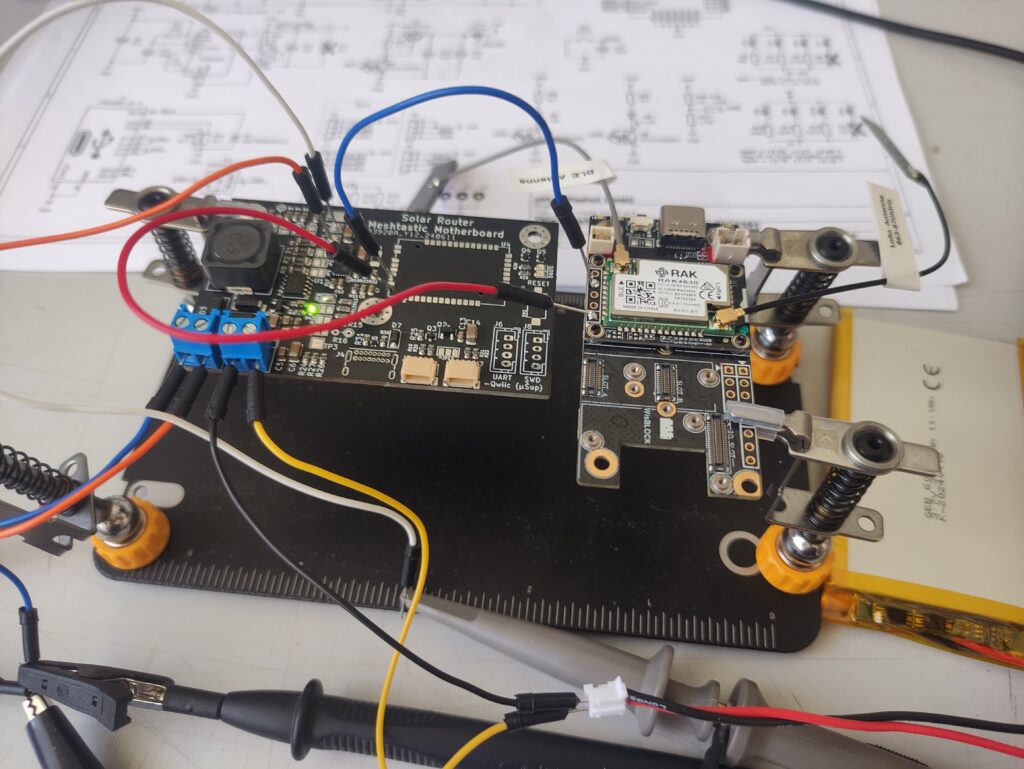
I added USB-C, connectors for I2C, and other necessities. The result is shown in the image below. PCB design, component selection, and preparation of production data took me a few weeks. Due to the small dimensions of some components (I’m looking at you, U2 and U3!), for the first time, I had to use the PCB assembly service.
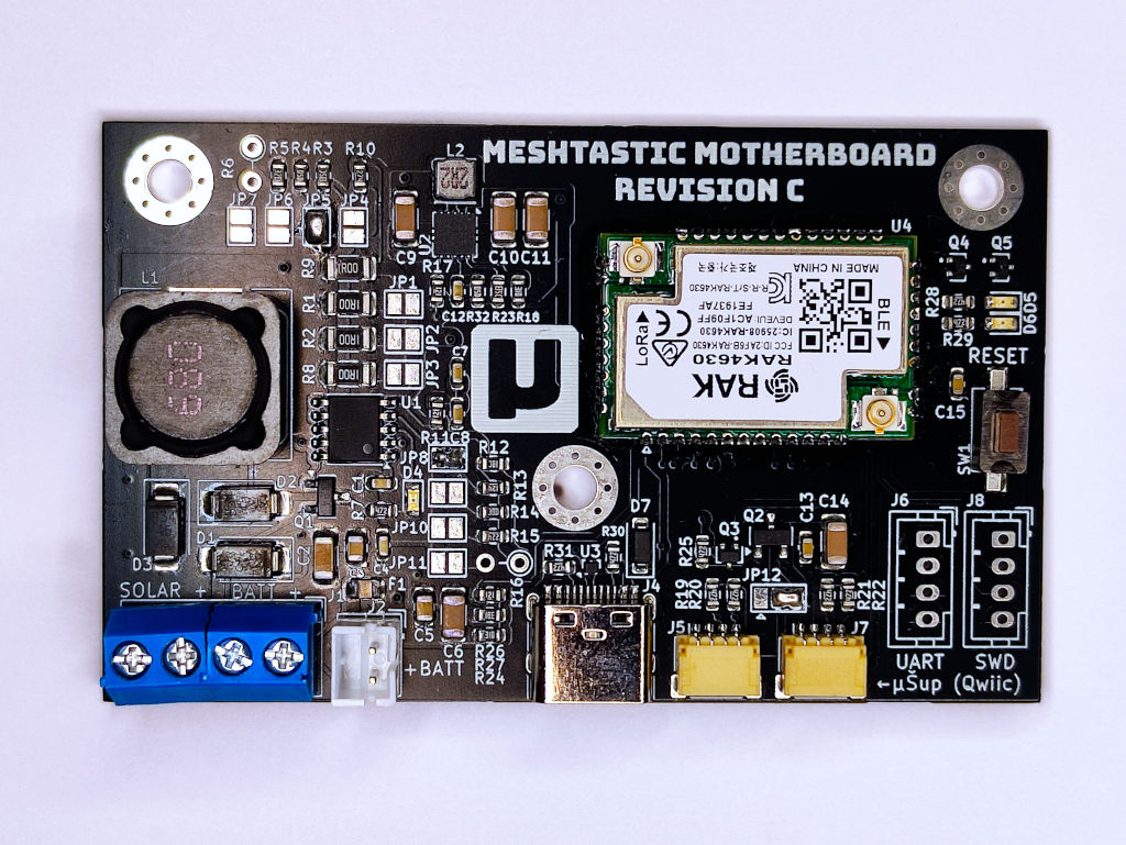
After selling all the pieces from the first production series, I made a few changes to the design, leading to revision B. It is functionally identical to revision A and contains only minor changes that helped with hand soldering:
- The power connectors J1 and J2 are closer together, allowing both screw connectors to be connected and soldered as one.
- I replaced the USB-C connector with a cheaper SMD variant and had it machine-assembled. Soldering the THT variant in revision A was time-consuming and the result wasn’t satisfactory.
- The reset button was swapped for another type.
- Resistor R13 was changed from 150 kΩ to 120 kΩ. This means when bridging JP8, it’s possible to power the B revision board from a 12V source instead of the original 13.8 V in revision A.
- Switch from „solid pad connections“ to „thermal reliefs“ for GND areas. Hand soldering of the radio module is now easier, as GND pads with thermal reliefs don’t conduct heat away as quickly.
Revision C brought further improvements:
- I added a 2-pin JST-PH connector for easier battery connection. Now you can choose between this connector (Li-Ion batteries usually have this kind of connector) and the original screw terminal.
- The battery now has an over-current protection. The PPTC fuse starts to react for currents >750 mA.
- Test points are all now on the bottom side, allowing for easier and quicker testing.
- Completely changed the layout of the buck-boost converter, now with larger copper surfaces and better GND around. Exactly as per the manufacturer’s recommendations.
- Slightly optimized the layout of the MPPT converter, brought its input and output capacitors closer to each other and made room for the aforementioned PPTC fuse.
- The back side now has a „Powered by Meshtastic“ logo.
Revision D:
- The RAK4630 module is not soldered by hand anymore but by a JLCPCB assembly service. This will lead to a more reliable product.
- The resistor R17 between VIN and VINA on the TPS6300 has been removed. Now the converter reliably starts with an input voltage of 1.8 V or higher. The original version could have stability issues with voltages between 1.8 and 2.2 V.
- QWIIC (STEMMA) connectors J5 and J7 are now on a single I2C bus, which allows easier connection of multiple sensors. The I2C2 pins are no longer used.
Revision E:
- The USB-C connector now also provides power to the RAK4630 module (but not for charging the battery). This makes firmware updates and experiments easier, as no external power supply or battery is needed.
- The name has been changed to “Solar Mesh Baseboard”. The word Meshtastic and its logo no longer appear on the PCB due to the Meshtastic™ trademark owned by Meshtastic LLC.
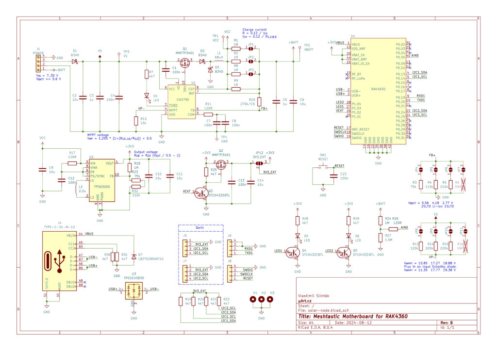
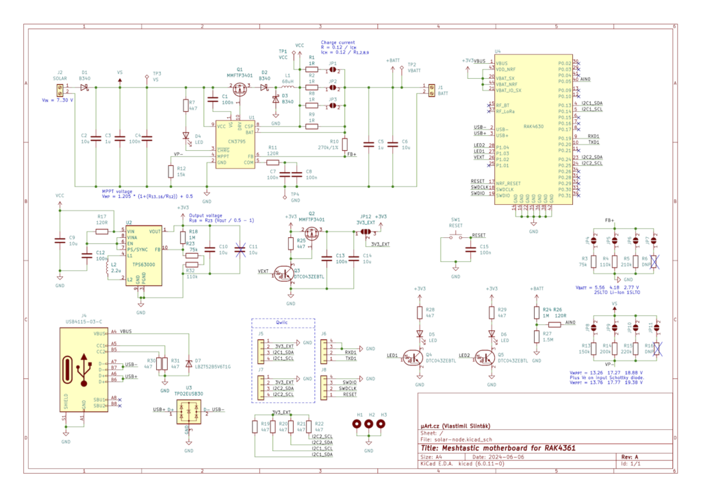
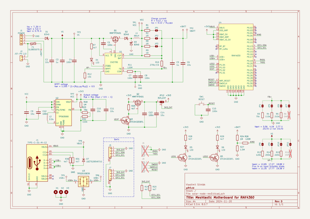
Useful Links
- Revision E
- Revision D
- Revision C
- Revision B
Board Settings
The PCB is designed universally, to (hopefully) suit everyone. Thanks to this, you can use any solar panel with a voltage from 7 to 30 V and batteries with various chemistry and capacity. The trade-off for universality is the need to set the correct parameters before the first use. This is done with several solder jumpers, so turn on your soldering irons, and let’s get started.
Differences in PCB revisions are explained wherever relevant. Most photographs show revision A, but the description applies to revisions B, C, and D as well.
Battery Charging
Solder bridges JP4 to JP7 serve to select the maximum charging voltage of the battery and JP1 to JP3 for the maximum charging current.
The charging voltage is the nominal voltage of the fully charged battery (e.g., 4.2 V for Li-Ion). To select your chosen battery, just connect/solder both pads of one jumper. Always select only one jumper! For LiFePo4 batteries or other less common chemistry, choose jumper JP7 and fit position R6 with a suitable THT resistor.
| Battery | Voltage | Jumper |
| 1S LTO | 2.77 V | JP6 |
| 1S Li-Ion or Li-Pol | 4.18 V | JP5 |
| 2S LTO | 5.56 V | JP4 |
| 1S LiFePo4 | 3.55 V | JP7 + resistor 140 kΩ |
| other type | < 5.6 V | JP7 + resistor \(R_{6} = \frac{326}{U_{BATT} – 1.22} [k\Omega]\) |
The maximum charge current is chosen using jumpers JP1 to JP3. If all jumpers are disconnected (default state), the charging maximum current is 120 mA. The circuit will never exceed the set current, even if the solar panel (voltage source) is sufficiently powerful. Conversely, the current may be lower if the solar panel cannot provide enough power.
If your battery has a larger capacity and you’re using a large solar panel, you can set a higher charge current by soldering both jumper pads of JP1 (240 mA), JP1+JP2 (360 mA), or JP1+JP2+JP3 (480 mA). This is the only setting where you can solder one or more jumpers at the same time.
I recommend setting the charging current to a maximum of 0.5 C for your battery. This means a maximum current of less than half the capacity. For example, a battery with a 500 mAh capacity can be charged a maximum of 250 mA, so jumper JP1 (240 mA) is fine. For a battery 1000 mAh or larger, you can set the maximum value of 480 mA (all jumpers soldered). Generally, a lower charging current increases battery lifespan and charging is safer even at higher ambient temperatures.
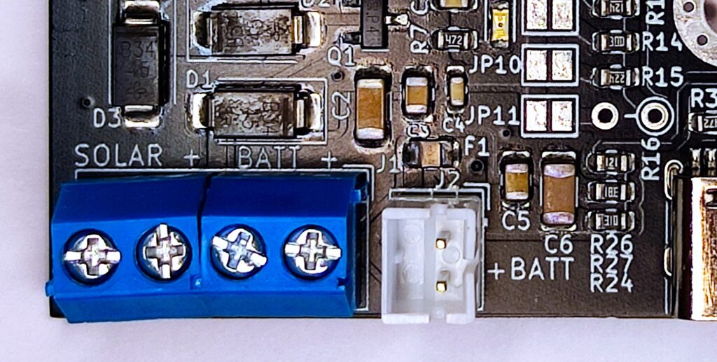
On PCB revisions C and D, the blue screw terminal labeled J1 (bottom left) and now also a white JST-PH connector J2 are available. Both can be used to connect your battery but always use one connector. Do not connect two different batteries to both connectors! Also, be careful of the battery polarity (for example, Li-Pol batteries with a JST-PH connector can have + and – connected differently in the connector).
Safety note: the baseboard does not contain under-voltage or over-current battery protection (revision C and D added over-current protection but still lacks under-voltage). This means the battery could discharge below the minimum allowable voltage, permanently damaging it. In revisions A and B, the battery is not protected in case of a short circuit or other fault causing a high discharge current. Therefore, always use batteries with built-in protection.
Note on LTO batteries: some manufacturers claim LTO batteries can be safely discharged to 0 V without permanent damage, only at the cost of reduced lifespan. If true, this means under-voltage protection is not required for LTO batteries and it’s feasible to connect these batteries without protection on PCB revisions C and D. However, I must emphasize this is a claim from some manufacturers and I haven’t tested it. Proceed at your own risk.
Solar Panel
Solder jumpers JP8 to JP11 are used to set the operating voltage of the solar panel UMPPT. Always solder only one jumper, the others must remain unconnected. For example, if your panel is 12V/10W with open-circuit voltage VOC=21.58 V and voltage at maximum power VMPPT=17.42 V, bridge jumper JP9, which sets the voltage to approximately 17.77 V, very close to the required VMPPT.
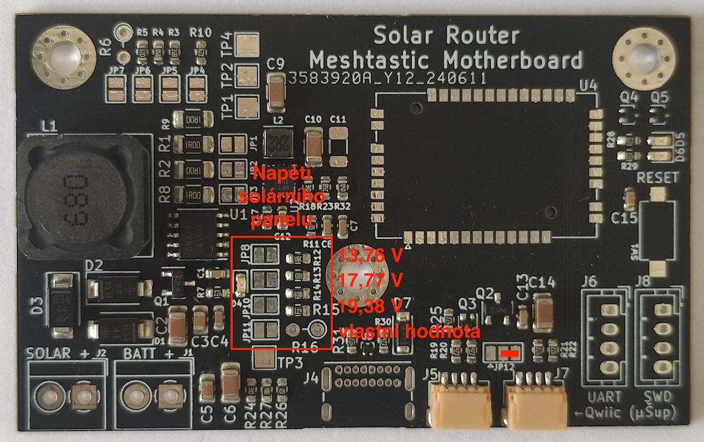
Other prepared VMPPT voltage values are 13.76 V; 17.77 V and 19.38 V for revision A, and 11.35 V; 17.77 V, and 19.38 V for revisions B, C and D. This is determined by resistors R13, R14, and R15. Jumper JP11 and the space for THT resistor R16 are prepared in case none of the preset voltages suit you. If you have a solar panel with a different value, simply solder a resistor at position R16 with a value:
\(R_{16} = R_{12} \cdot \frac{V_{MPPT} – 1.705}{1.205} \)where \(R_{16}\) is the resistor value we look for in kΩ, \(R_{12}\) is the resistor value 15 kΩ, and \(V_{MPPT}\) is the operating voltage at maximum power of the solar panel.
| \(V_{MPPT}\) | \(R_{16}\) | Jumper |
| 13.76 V (rev A) 11.35 V (rev B, rev C, rev D) | 150 kΩ (rev A) 120 kΩ (rev B) | JP8 |
| 17.77 V | 200 kΩ | JP9 |
| 19.38 V | 220 kΩ | JP10 |
| 9.74 V | 100 kΩ | JP11 + R16 |
| 11.35 V | 120 kΩ | JP11 + R16 |
Power from Source (UPS Mode)
The board can be powered from a voltage source instead of a solar panel. This is useful, for instance, when you have a nearby power supply available for the Meshtastic node. This way, the baseboard will be permanently powered from the source, and the battery will serve only as backup during occasional power outages.
For this mode, no special setup is needed. Simply connect your source to the SOLAR connector terminals (be careful about the polarity) and set the correct voltage on the jumpers JP8 to JP11 (see the „solar panel“ section above).
The set VMPPT voltage must be lower than the voltage of the used source. For PCB revision A and a source with a nominal voltage of 12 V DC, I recommend bridging jumper JP11 and setting resistor R16 to 120 kΩ. For PCB revisions B and C, it’s easier; just bridge jumper JP8 and use a 12 V source.
PCB revision A: For sources with a nominal voltage of 13 to 17 V, I recommend bridging jumper JP8, for voltages 17 to 20 V jumper JP9, and for 20 to 30 V jumper JP10. The precise value isn’t as important, the electronics will handle stabilization and battery charging.
PCB revisions B, C and D: For sources with a nominal voltage of 12 to 17 V, I recommend bridging jumper JP8, for voltages 17 to 20 V jumper JP9, and for 20 to 30 V jumper JP10. The precise value isn’t as important, the electronics will handle stabilization and battery charging.
Antennas
The RAK4630 module has two IPEX connectors for LoRa and Bluetooth radios. A label on the module indicates which connector belongs to which radio.
You can connect either a small antenna with an IPEX connector or a short IPEX-SMA cable and use an antenna with an SMA connector. The choice of antenna and cables is yours; they are not included in the package.
Flexible antennas from the manufacturer Gizont are popular among Meshtastic enthusiasts. This Chinese manufacturer offers a LoRa antenna for a frequency of 868 MHz with a length of 167 mm. The connector on the antenna varies, but most commonly, an SMA-RP is used for Meshtastic.
- IPEX to SMA cable (pigtail) on Aliexpress. Choose the variant „IPEX to RPSMA-K“.
- Bluetooth antenna with IPEX (2,4 GHz; same frequency as WiFi) on Aliexpress.
- LoRa (868 MHz) antenna manufactured by Gizont on Aliexpress. Choose the variant „RP-SMA M“.
Warning! Never power on the board without connected antennas. Transmission power may damage the radio’s electronics, either completely destroying it or reducing its sensitivity.
Connectors
The PCB is equipped with two JST-SH SM04B connectors, also known as Qwiic (from Sparkfun) or μŠup (from Czech seller Laskakit). One connector (J5) is connected to I2C1 of the RAK4630 module, and the other connector (J7) is connected to I2C2. Since revision D, both connectors are connected to the I2C1 bus, so both can be used for your sensors.
By using the solder bridge JP12, you can choose whether sensors on I2C should be permanently powered (bridge connected to the right) or only temporarily, with power controlled from the RAK (bridge connected to the left; this control using pin P1.02 on RAK4630 is not yet tested).
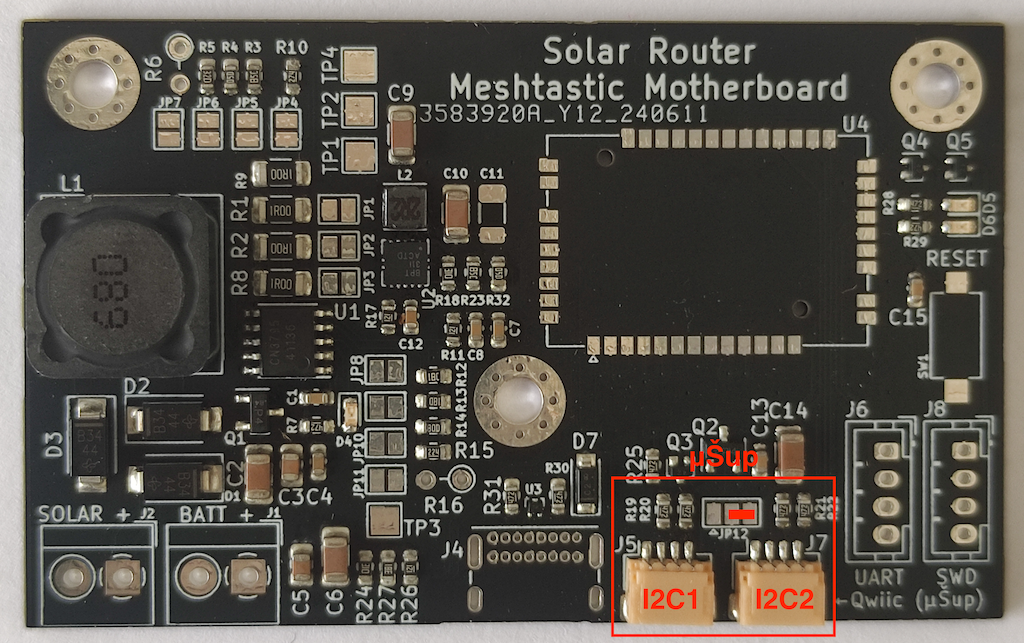
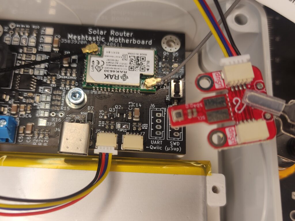
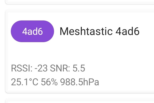
If you turn on the „telemetry“ module in the standard Meshtastic firmware, the sensors connected to I2C1 will automatically initialize and their measurements will automatically be sent to the network. This is helpful, for example, with a BME280 sensor (measuring temperature, humidity, and pressure). The Laskakit shop offers BME280 with a μŠup connector, making a connection to the Meshtastic baseboard easy, as shown in the photo below. Then, in the telemetry settings, simply enable „Environment Telemetry Enabled“ and set the measurement interval „Environment Metrics Update Interval“.
Boards with revision D have both connectors on the I2C1 bus, so you can use both of them for any supported sensor.
Physical Dimensions
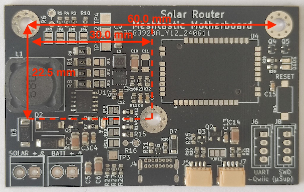
The overall dimensions of the PCB are 70×43 mm. The position of the holes for M3 screws is shown in the photo below.
Firmware
I’ve already programmed the RAK4630 module with the correct bootloader via the SWD interface, making uploading the Meshtastic firmware straightforward via the USB interface.
- Connect the board to a power supply (for instance, by connecting a charged battery).
- Connect the USB-C cable to the board and your PC (running Linux, Mac OS, or Windows).
- Press the RESET button twice quickly. This switches the module to USB Mass Storage mode, and a new drive will appear on your PC.
- Copy the Meshtastic FW in uf2 format, suitable for RAK4631, onto this drive.
- After copying is completed, the drive will automatically disconnect, and the RAK module will restart.
- Done. The new firmware is now running, and you can control it either via the serial interface (USB) or Bluetooth as a standard Meshtastic node.
Questions and Additional Information
This solar charger is the first more complex circuit that I’m offering for sale. I’m continuously learning and improving where I can, but it’s possible I may have forgotten to mention some essential information or that some parts of the electronics don’t work as described. If you encounter any problems, feel free to contact me either by email or via Twitter.
Thank you for your interest in my design 🙏 and I wish you lots of fun with Meshtastic.

